

Grove Beginner Kit For Arduino: Codecraft Lesson 10 - Sensing-movement
ardrpi arduino
Reading and responding to the triaxial accelerometer. THIS LESSON DOES NOT WORK AS THE CODECRAFT 3 AXIS SENSOR COMPONENT IS NOT THE ONE IN THE BEGINNERS KIT.
| The Grove Beginner Kit For Arduino includes an Arduino Uno board with preconnected devices. The Grove lessons supporting this present coding using the Arduino IDE. These pages present the same lessons using the Codecraft IDE that uses the Block style of coding with specific Grove Arduino blocks. |
This is the last sensor, the triaxial accelerometer, and with this module, you can easily add motion monitoring to your design. So we can do a lot of interesting little experiments on the basis of the motion.
- Practice: when motion is detected, the buzzer gives an alarm indicating that the object is in motion.
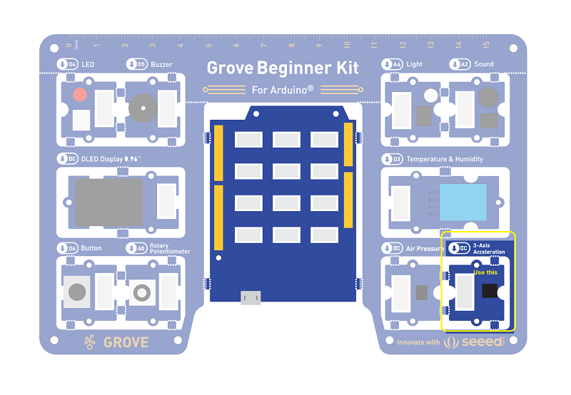
Grove Beginners Kits Components
| Component | Interface | Pins/Address |
|---|---|---|
| LED | Digital | D4 |
| Buzzer | Digital | D5 |
| ==OLED Display 0.96”== | ==I2C== | ==I2C, 0x78(default)== |
| Button | Digital | D6 |
| Rotary Potentiometer | Analog | A0 |
| Light | Analog | A6 |
| Sound | Analog | A2 |
| Temperature & Humidity Sensor | Digital | D3 |
| Air Pressure Sensor | I2C | I2C, 0x77(default) / 0x76(optional) |
| ==3-Axis Accelerator== | ==I2C== | ==I2C, 0x19(default)== |
Components used for this lesson are highlighted.
-
Components Involved
- Grove Beginner Kit
- Grove 3-axis Accelerometer
2. Implement the code block.
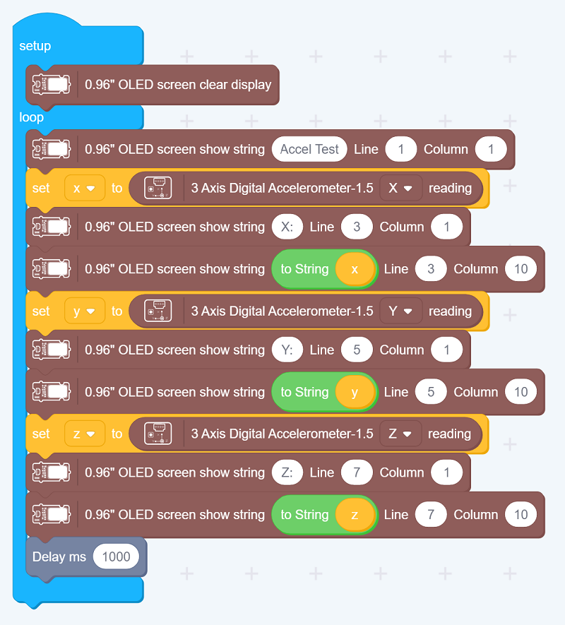
How to create this …
Watch the video on Youtube:
2Do: Ignore as this is a place holder.
3. Run the app
Download the app to the board, as in previous lesson
Outcome:
The 3-axis accelerator readings are displayed on the Serial Monitor.
-
Hardware connection
- Module connection:
- Default connection by PCB stamp hole.
- The Seeeduino is then connected to the computer via a USB cable.
- Module connection:
-
Software Code
- Open Arduino IDE.
- Download the 3-Axis Digital Accelerometer( ±2g to 16g) from Github. Click on Sketch > Include library > Add .ZIP library, import the library into the IDE.
- Copy the following code, click Verify to check for syntax errors. Verify that there are no errors, and you can upload the code.
- In this program, acceleration information is sent from the sensor to Seeeduino via I2C bus and then Seeeduino printed them onto the serial monitor. Open the serial monitor to check the result.
//Gravity Acceleration
#include "LIS3DHTR.h"
#ifdef SOFTWAREWIRE
  #include <SoftwareWire.h>
  SoftwareWire myWire(3, 2);
  LIS3DHTR<SoftwareWire> LIS;     //Software I2C
  #define WIRE myWire
#else
  #include <Wire.h>
  LIS3DHTR<TwoWire> LIS;       //Hardware I2C
  #define WIRE Wire
#endif

void setup() {
  Serial.begin(9600);
  while (!Serial) {};
  LIS.begin(WIRE, 0x19); //IIC init
  delay(100);
  LIS.setOutputDataRate(LIS3DHTR_DATARATE_50HZ);
}
void loop() {
  if (!LIS) {
    Serial.println("LIS3DHTR didn't connect.");
    while (1);
    return;
  }
  //3 axis
  Serial.print("x:"); Serial.print(LIS.getAccelerationX()); Serial.print("  ");
  Serial.print("y:"); Serial.print(LIS.getAccelerationY()); Serial.print("  ");
  Serial.print("z:"); Serial.println(LIS.getAccelerationZ());

  delay(500);
}
- Code Analysis
#include "LIS3DHTR.h"
#ifdef SOFTWAREWIRE
  #include <SoftwareWire.h>
  SoftwareWire myWire(3, 2);
  LIS3DHTR<SoftwareWire> LIS;   //Software I2C
  #define WIRE myWire
#else
  #include <Wire.h>
  LIS3DHTR<TwoWire> LIS;    //Hardware I2C
  #define WIRE Wire
#endif
Initializing the module using software I2C or hardware I2C.
while (!Serial) {};
Code stops here if don’t open the serial monitor, so open serial monitor.
LIS.begin(WIRE, 0x19);
LIS.setOutputDataRate(LIS3DHTR_DATARATE_50HZ);
Description: Initialize the accelerator.
Syntax: LIS.begin(Wire, address).
Description: Sets the output data rate of the accelerator.
Syntax: LIS.setOutputDataRate(odr_type_t odr).
Initialize the accelerator and set the output rate to 50Hz.
Serial.print("x:"); Serial.print(LIS.getAccelerationX()); Serial.print("  ");
Serial.print("y:"); Serial.print(LIS.getAccelerationY()); Serial.print("  ");
Serial.print("z:"); Serial.println(LIS.getAccelerationZ());
Description:
Functions to be used to read X-axis value from the sensor.
Syntax:
LIS.getAccelerationX(). Return type: float.
Description:
Functions to be used to read Y-axis value from the sensor.
Syntax:
LIS.getAccelerationY(). Return type: float.
Description:
Functions to be used to read Z-axis value from the sensor.
Syntax:
LIS.getAccelerationZ(). Return type: float.
Prints the 3 axis data to the serial monitor.
Demo Effect and Serial Print Result:
The 3-axis accelerator readings are displayed on the Serial Monitor.
Music dynamic rhythm lamp
-
Project description: In this experiment, we will make the buzzer play pleasant music and the led lights flash according to the music frequency and beat.
-
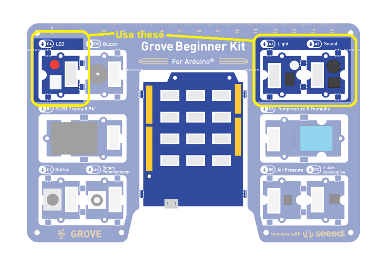
Components Involved
- Grove Beginner Kit
- Grove LED
- Buzzer
- Grove Cables(if broken out)

-
Hardware connection
- Module connection:
- Default connection by PCB stamp hole.
- The Seeeduino is then connected to the computer via a USB cable.
- Module connection:
-
Software Code
- Open Arduino IDE.
- Copy the following code, click Verify to check for syntax errors. Verify that there are no errors, and you can upload the code.
//Music Dynamic Rhythm Lamp
#define NTD0 -1
#define NTD1 294
#define NTD2 330
#define NTD3 350
#define NTD4 393
#define NTD5 441
#define NTD6 495
#define NTD7 556

#define NTDL1 147
#define NTDL2 165
#define NTDL3 175
#define NTDL4 196
#define NTDL5 221
#define NTDL6 248
#define NTDL7 278

#define NTDH1 589
#define NTDH2 661
#define NTDH3 700
#define NTDH4 786
#define NTDH5 882
#define NTDH6 990
#define NTDH7 112

#define WHOLE 1
#define HALF 0.5
#define QUARTER 0.25
#define EIGHTH 0.25
#define SIXTEENTH 0.625

int tune[]=
{
NTD3,NTD3,NTD4,NTD5,
NTD5,NTD4,NTD3,NTD2,
NTD1,NTD1,NTD2,NTD3,
NTD3,NTD2,NTD2,
NTD3,NTD3,NTD4,NTD5,
NTD5,NTD4,NTD3,NTD2,
NTD1,NTD1,NTD2,NTD3,
NTD2,NTD1,NTD1,
NTD2,NTD2,NTD3,NTD1,
NTD2,NTD3,NTD4,NTD3,NTD1,
NTD2,NTD3,NTD4,NTD3,NTD2,
NTD1,NTD2,NTDL5,NTD0,
NTD3,NTD3,NTD4,NTD5,
NTD5,NTD4,NTD3,NTD4,NTD2,
NTD1,NTD1,NTD2,NTD3,
NTD2,NTD1,NTD1
};

float durt[]=
{
1,1,1,1,
1,1,1,1,
1,1,1,1,
1+0.5,0.5,1+1,
1,1,1,1,
1,1,1,1,
1,1,1,1,
1+0.5,0.5,1+1,
1,1,1,1,
1,0.5,0.5,1,1,
1,0.5,0.5,1,1,
1,1,1,1,
1,1,1,1,
1,1,1,0.5,0.5,
1,1,1,1,
1+0.5,0.5,1+1,
};

int length;
int tonepin=5;
int ledp=4;

void setup()
{
  pinMode(tonepin,OUTPUT);
  pinMode(ledp,OUTPUT);
  length=sizeof(tune)/sizeof(tune[0]);
}

void loop()
{
  for(int x=0;x<length;x++)
  {
  tone(tonepin,tune[x]);
  digitalWrite(ledp, HIGH);
  delay(400*durt[x]);
  digitalWrite(ledp, LOW);
  delay(100*durt[x]);
  noTone(tonepin);

  }
  delay(4000);
}
- Code Analysis
#define NTD
Here is the definition of the frequency of the D key, which is divided into bass, alto, and treble.
#define WHOLE 1
#define HALF 0.5
#define QUARTER 0.25
#define EIGHTH 0.25
#define SIXTEENTH 0.625
Note: rhythm is divided into one beat, half beat, ¼ beat, ⅛ beat, we specify a beat note time is 1;Half beat is 0.5;¼ beat is 0.25;⅛ of 0.125.
int tune[]=...
List the frequencies according to the spectrum.
float durt[]=...
List the beats according to the spectrum.
delay(100*durt[x]);
Control LED lights on and off respectively.
Demo Effect and Serial Print Result:
The buzzer will beep a tune while the LED module will flicker with same frequency.
- Breakout Guide
Connect Grove LED to Grove Beginner Kit’s digital signal interface D4, connect Buzzer to Grove Beginner Kit’s digital signal interface D5.
Project 2: Make an intelligent sound-light induction desk lamp
-
Project description: as the name implies, this project is to make a small lamp controlled by Sound and Light. We need to use the LED module as output. Light sensor and sound sensor are used for input signals. In this way, you can achieve the function of the smart desk lamp: if the surrounding sound level is above certain pre-set value, then the LED light up, or if the surrounding light intensity is below certain value, the LED module also light up.
-
Components Involved
- Grove Beginner Kit
- Grove LED
- Light Sensor
- Sound Sensor
-
Hardware connection
- Module connection:
- Default connection by PCB stamp hole.
- The Seeeduino is then connected to the computer via a USB cable.
- Module connection:
-
Software Code
- Open Arduino IDE.
- Copy the following code, click Verify to check for syntax errors. Verify that there are no errors, and you can upload the code.
//light Induction Desk Lamp
int soundPin = A2; // Analog sound sensor is to be attached to analog
int lightPin = A6; //Analog light sensor is to be attached to analog
int ledPin = 4; // Digital LED is to be attached to digital

void setup() {
  pinMode(ledPin, OUTPUT);
  pinMode(lightPin, INPUT);
  pinMode(soundPin, INPUT);
}

void loop(){
  int soundState = analogRead(soundPin); // Read sound sensor’s value
  int lightState = analogRead(lightPin); // Read light sensor’s value
  // if the sound sensor's value is greater than 500 or the sound sensor's is less than 200, the light will be on.
  //Otherwise, the light will be turned off
if (soundState > 500 || lightState < 200) {
  digitalWrite(ledPin, HIGH);
  delay(500); //You can add the "//" to remove the delay
}else{
  digitalWrite(ledPin, LOW);
}
}
- Code Analysis
if (soundState > 500 || lightState < 200) {
  ...
}
| In parentheses is a logical expression. Both && and ** | ** are commonly used in logical expressions. The common usage is **if (expression 1 | expression 2)** and if (expression 1 && expression 2). |
| ** | ** represents “or”, satisfies one of them, the whole expression is true, and satisfies the condition of the if judgment. |
&& means “and”, the statement in if{} is executed only if all expressions in parentheses are true.
Demo Effect and Serial Print Result:
If the surrounding sound is loud enough or light intensity is low, the LED module will light up more intensity.
| Topic | Subtopic | |
| This Category Links | ||
| Category: | Grove Arduino Index: | Grove Arduino |
| Next: > | Grove Beginner Kit For Arduino | The Cloud |
| < Prev: | Grove Beginner Kit For Arduino | Codecraft Lesson 9 - Measuring Surrounding Air Pressure |