

Softata - Adding a new display: 1. The Display Hardware
softata rpipico firmata arduino csharp bme280 grove softatadisplay
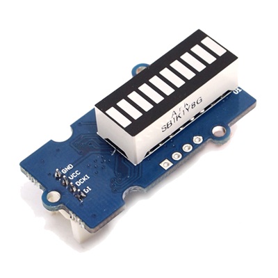
An example of adding a display to Softata … The Bargraph Hardware.
It is proposed to add a linear Bargraph display the Softata suite as a display. It is intended that it it conform to the required methods of Softata.Display class as well as having some custom device specific Misc methods.
There is a Grove LED Bar Display that could be used for this purpose. A latter manifestation may include this at a later stage.
Tap and rotate phone to enlarge.
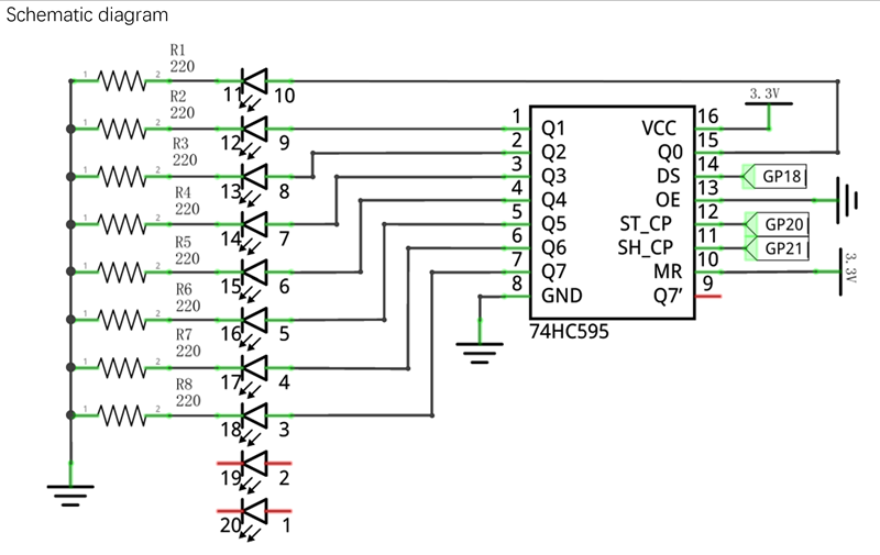
The current exercise uses a solution from Freenove using an off-the-shelf Bargraph and a 74HC595. This clocks an 8 bit number into a 74HC595 thus using 3 pins:
- Data
- Clock
- Latch
This means 3 pins of the Pico are required rather 9 or 10 if the data was sent in parallel. I2C would only be 2 though.
Nb: A 10 segment is illustrated although only 8 (8 bits) are used.
The Arduino shiftout() command performs the shifting of the whole 8 bits of data without further direction:
// Output low level to latchPin
 digitalWrite(latchPin, LOW);
// Send serial data to 74HC595
  shiftOut(dataPin, clockPin, order, data);
// Output high level to latchPin, and 74HC595 will update the data to the parallel output port.
  digitalWrite(latchPin, HIGH);
The latch is disabled and re-enabled immediately before and after this transmission. The Order parameter sets the direction in which the bit are transmitted, lower bits first or higher bits first:
- LSBFIRST
- MSBFIRST
And the display of the shifted bits (one per segment) are only updated after the latch goes high.
Tap and rotate phone to enlarge.
The Bargraph Schematic
Test Arduino Sketch
/**********************************************************************
  Filename    : FlowingLight.ino
  Description : Use 74HC595 to drive the ledbar to display the flowing light.
  Source      : www.freenove.com
**********************************************************************/
int dataPin = 16;   // Pin connected to DS of 74HC595(Pin14)
int latchPin = 20;  // Pin connected to ST_CP of 74HC595(Pin12)
int clockPin = 21;  // Pin connected to SH_CP of 74HC595(Pin11)

void setup() { // set pins to output
  pinMode(latchPin, OUTPUT);
  pinMode(clockPin, OUTPUT);
  pinMode(dataPin, OUTPUT);
}

void loop() {
  // Define a one-byte variable to use the 8 bits to represent the state of 8 LEDs of LED bar graph.
  // This variable is assigned to 0x01, that is binary 00000001, which indicates only one LED light on.
  byte x = 0x01;    // 0b 0000 0001
  for (int j = 0; j < 8; j++) { // Let led light up from right to left
    writeTo595(LSBFIRST, x);
    x <<= 1; // make the variable move one bit to left once, then the bright LED move one step to the left once.
    delay(1000);
  }
  delay(100);
  x = 0x80;       //0b 1000 0000
  for (int j = 0; j < 8; j++) { // Let led light up from left to right
    writeTo595(LSBFIRST, x);
    x >>= 1;
    delay(1000);
  }
  delay(100);
}
void writeTo595(BitOrder order, byte _data ) {
  // Output low level to latchPin
  digitalWrite(latchPin, LOW);
  // Send serial data to 74HC595
  shiftOut(dataPin, clockPin, order, _data);
  // Output high level to latchPin, and 74HC595 will update the data to the parallel output port.
  digitalWrite(latchPin, HIGH);
}
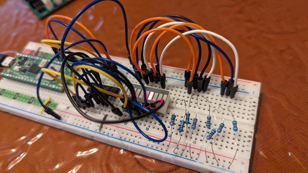
Prototype Hardware
A “prototype” was built on a Breadboard the test the sample sketch and for initial Softata implementation of the Bargraph support:
Tap and rotate phone to enlarge.
Breadboard Implementation
A bit of a rats nest but it works! A better version coming.
Required Steps
- Create the prototype.
- Run the sketch
Follow up
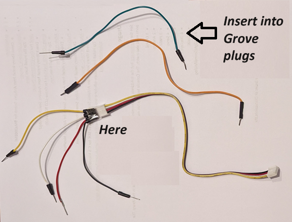
Using 2 x Grove cables with plug on one end and bare wires connect bare ends to the 3 prototype connection points.
- You can create “bare ends” by cutting a cable in half.
- I prefer to insert male jumper cables thus:
Tap and rotate phone to enlarge.
First cable
- Red and black wires to 3,3V and Gnd respectively
- White (to go to GP20) to ST_CP (74HC595 Pin12)
- Yellow (to go GP21) to SH_CP (74HC595 Pin11)
Second cable
Only the white cable needed but power and ground can be connected:
- White (to go to GP16) to DS (74HC595 Pin14)
Connecting to the Grove Pico Shield
- Connect the first cable to the D20 socket.
(The socket bottom right, see below.) - Connect the second cable to the D16 socket.
(The socket 3rd from right at bottom, see below)
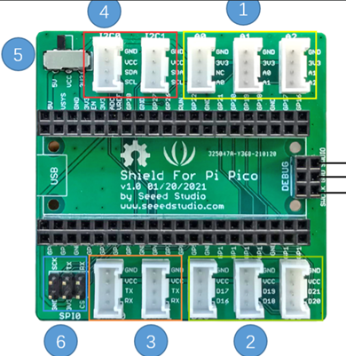
Tap and rotate phone to enlarge.
The 3 sockets in section 2 are the GPIO sockets. (D16/17,D18/19,D20/21).
- Section 1 Analog (A0,A1/A0,A2/A1)
- Section 2 I2C (I2C0,I2C1)
- Section 3 Serial (Serial1, Serial2)
Next: Creating a working “shell”, with null functionality, in Softata for a new Display.
| Topic | Subtopic | |
| This Category Links | ||
| Category: | Softata Index: | Softata |
| Next: > | Softata - Adding a new display | 2. The Software Specifications |
| < Prev: | Softata | About (Latest) |