

Grove Beginner Kit For Arduino: Codecraft Lesson 3 - Controlling the Frequency of the Blink
ardrpi arduino
This lesson introduces Analog to Digital conversion. The LED flash rate is controlled by the Rotary Potentiometer.
| The Grove Beginner Kit For Arduino includes an Arduino Uno board with preconnected devices. The Grove lessons supporting this present coding using the Arduino IDE. These pages present the same lessons using the Codecraft IDE that uses the Block style of coding with specific Grove Arduino blocks. |
In the last section, we studied that button only has two states, ON/OFF state corresponding 0V and 5V, but in practice, we often counter the need for many states, not just 0V and 5V. Then you need to use Analog Signal! Rotary Potentiometer is a classic example that uses an analog signal.
Background Information:
- What is Analog Signal
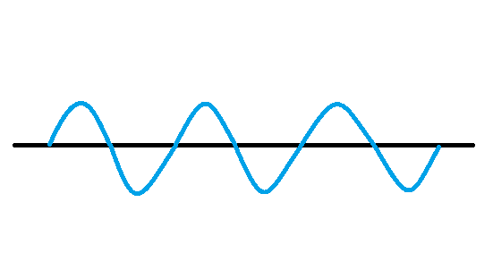
Analog signals: Signals vary continuously in time and value, and the amplitude, frequency, or phase of the signal changes continuously at any time, such as the current broadcast sound signal, or image signal, etc. The analog signal has sine wave and triangle wave and so on. The analog pins of your microcontroller can have between 0V and 5V is mapped to a range between 0 and 1023 where 1023 is mapped as 5V and 512 is mapped as 2.5v and etc.
Grove Beginners Kits Components
| Component | Interface | Pins/Address |
| LED | Digital | D4 |
| Buzzer | Digital | D5 |
| OLED Display 0.96” | I2C | I2C, 0x78(default) |
| Button | Digital | D6 |
| Rotary Potentiometer | Analog | A0 |
| Light | Analog | A6 |
| Sound | Analog | A2 |
| Temperature & Humidity Sensor | Digital | D3 |
| Air Pressure Sensor | I2C | I2C, 0x77(default) / 0x76(optional) |
| 3-Axis Accelerator | I2C | I2C, 0x19(default) |
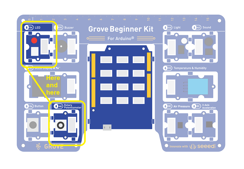
Components used for this lesson are highlighted.
- Components Involved
- Grove Beginner Kit
- Grove LED
- Grove Rotary Switch
The input is an analog signal, so it is connected to the analog signal interface, the LED module is connected to the digital signal interface.
2. Implement the code block.
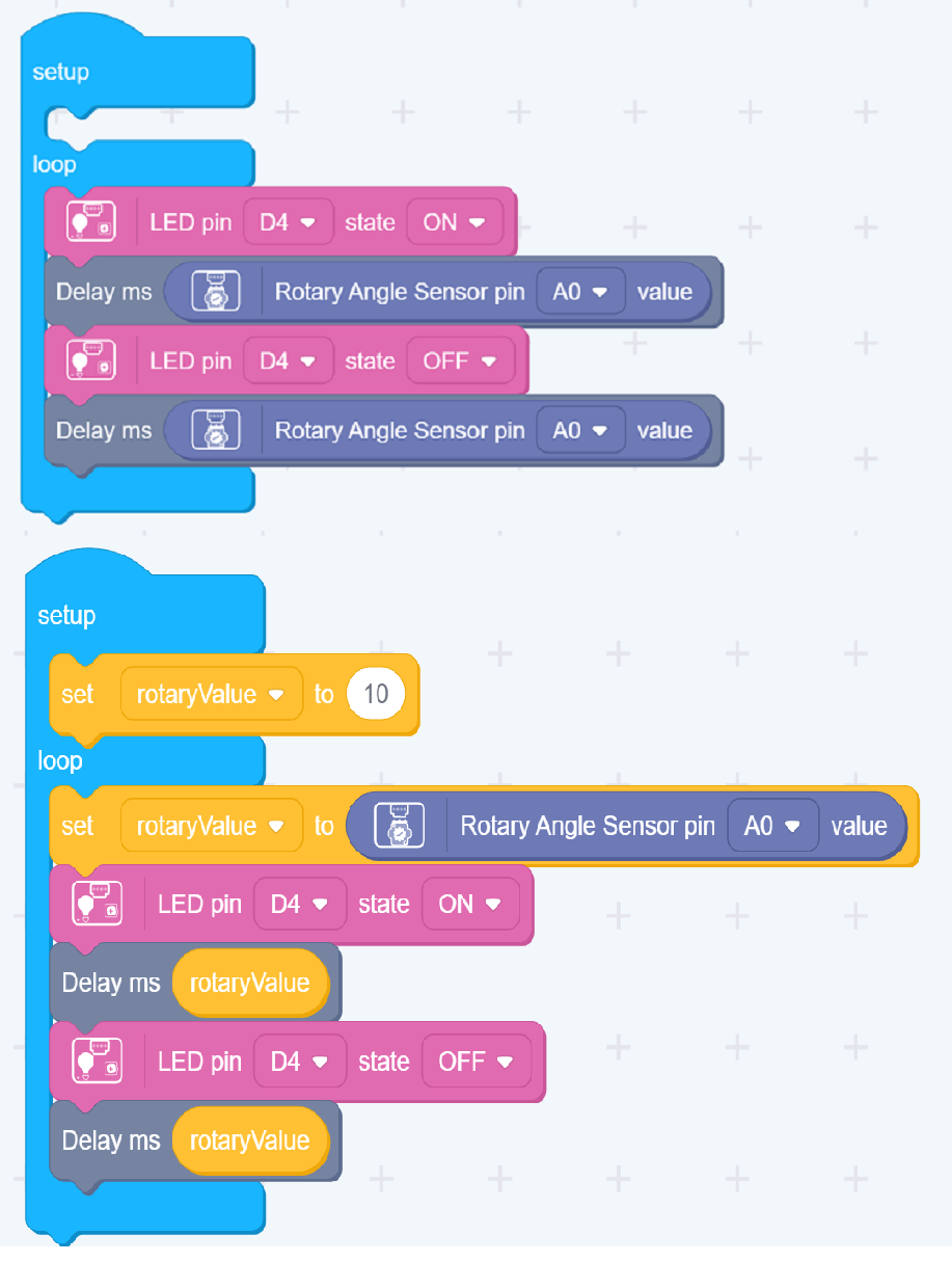
There are two ways to implement this lesson as shown. The first is simpler. The second introduces using variables. The following video demonstrates the second method.
How to create this …
Watch the video on Youtube:
3. Run the app
Download the app to the board, as in an earlier lesson.
Discussion
The loop function is similar to the previous 2 lessons. In the first there was a fixed delay between toggling the LED state. In the second the LED just tracked the state of the button press. In this lesson the on/off periods are set by the rotatry button that is input as an analog signal which when digitised gives a value of 0 to 1024. That results in periods of 0 to slighly more than one second.
This lesson shows how to define a variable, set an initial value (in setup) and to change it according to an Analog To Digital (ADC) conversion.
Outcome:
Turning the Potentiometer will change the frequency of LED flickering.
| Topic | Subtopic | |
| This Category Links | ||
| Category: | Grove Arduino Index: | Grove Arduino |
| Next: > | Grove Beginner Kit For Arduino | Codecraft Lesson 4 - Making the Buzzer go BEEP |
| < Prev: | Grove Beginner Kit For Arduino | Codecraft Lesson 2 - Pressing Button to light up LED |