

Grove Beginner Kit For Arduino: Codecraft Lesson 4 - Making the Buzzer go BEEP
ardrpi arduino
Controlling the buzzer by sending an oscillating digital signal to it, like the flashing LED. The signal used for the (passive) buzzer is PWM.
| The Grove Beginner Kit For Arduino includes an Arduino Uno board with preconnected devices. The Grove lessons supporting this present coding using the Arduino IDE. These pages present the same lessons using the Codecraft IDE that uses the Block style of coding with specific Grove Arduino blocks. |
Just like the LED module, Buzzer is also an output module, instead of lighting up it produces a beep sound. This can be used for many situations for indication purposes.Let’s learn how to generate sound using the buzzer!
Background Information:
- What is the difference between Active and Passive Buzzer
There are two types of buzzers, one is active and the other is passive. Both active and passive buzzers are used to make sound to electronics.
The active buzzer has an internal oscillation source that makes the buzzer sound whenever power is applied. Active buzzers are widely used in computers, printers, copiers, alarms, electronic toys, car electronics, telephones, timers and other electronic product sounding devices.
A passive buzzer has no internal source of oscillation and needs to be driven by a square wave and a different frequency. It acts like an electromagnetic speaker, and the changing input signal produces sound, rather than a tone automatically.
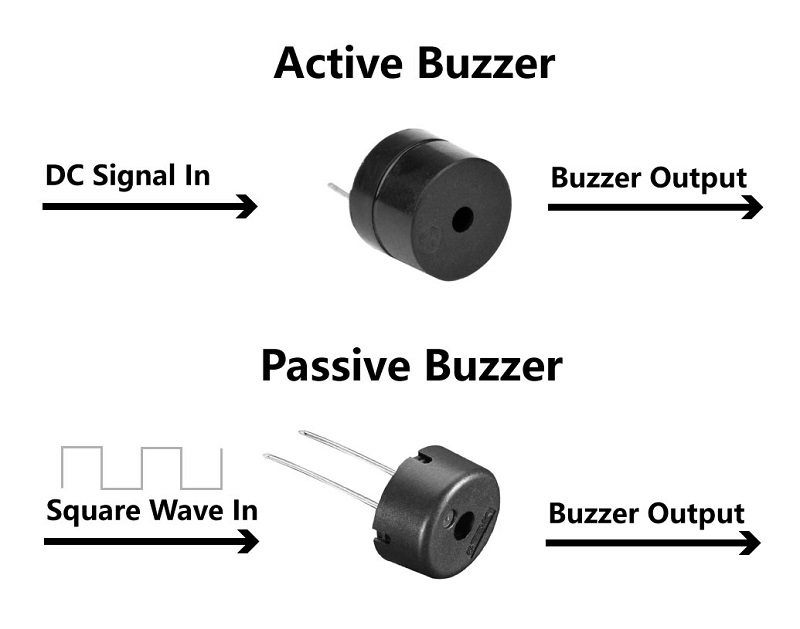
In this kit, the Grove-Buzzer is a passive buzzer so that it needs an AC signal to control it. This then leads to the next question, how to generate Square Wave(AC signals) with Arduino! Well, an easy way is to use PWM.
- What is PWM
Pulse Width Modulation, or PWM, is a technique for getting analog results with digital means. Digital control is used to create a square wave, a signal switched between on and off. This on-off pattern can simulate voltages in between full on (5 Volts) and off (0 Volts) by changing the portion of the time the signal spends on versus the time that the signal spends off. The duration of “on time” is called the pulse width. To get varying analog values, you change, or modulate, that pulse width. If you repeat this on-off pattern fast enough, the result is as if the signal is a steady voltage between 0 and 5v as a AC signal. Reference: Arduino. This PWM signal can then be used to control the passive buzzer with ease.
To generate PWM signals in Arduino, you can use analogWrite(), in contrast to using digitalWrite() to generate DC signals.
There are six digital pins on your Seeeduino that are marked with the symbol “~”, which means they can send out a PWM signal : 3,5,6,9,10,11. They are celled PWM pins. For the Buzzer 5 is used.
Grove Beginners Kit Components
| Component | Interface | Pins/Address |
|---|---|---|
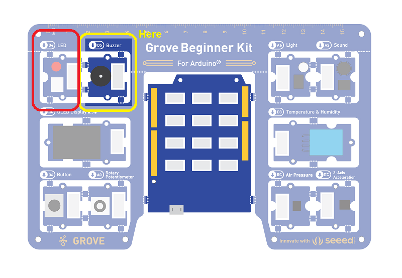
| ==LED== | ==Digital== | ==D4== |
| ==Buzzer== | ==Digital== | ==D5== |
| OLED Display 0.96” | I2C | I2C, 0x78(default) |
| ==Button== | ==Digital== | ==D6== |
| Rotary Potentiometer | Analog | A0 |
| Light | Analog | A6 |
| Sound | Analog | A2 |
| Temperature & Humidity Sensor | Digital | D3 |
| Air Pressure Sensor | I2C | I2C, 0x77(default) / 0x76(optional) |
| 3-Axis Accelerator | I2C | I2C, 0x19(default) |
Components used for this lesson are highlighted.
- Components Involved
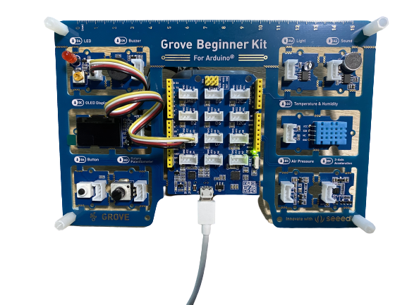
- Grove Beginner Kit
- Grove Buzzer
- Grove LED & Button
2. Implement the code block.
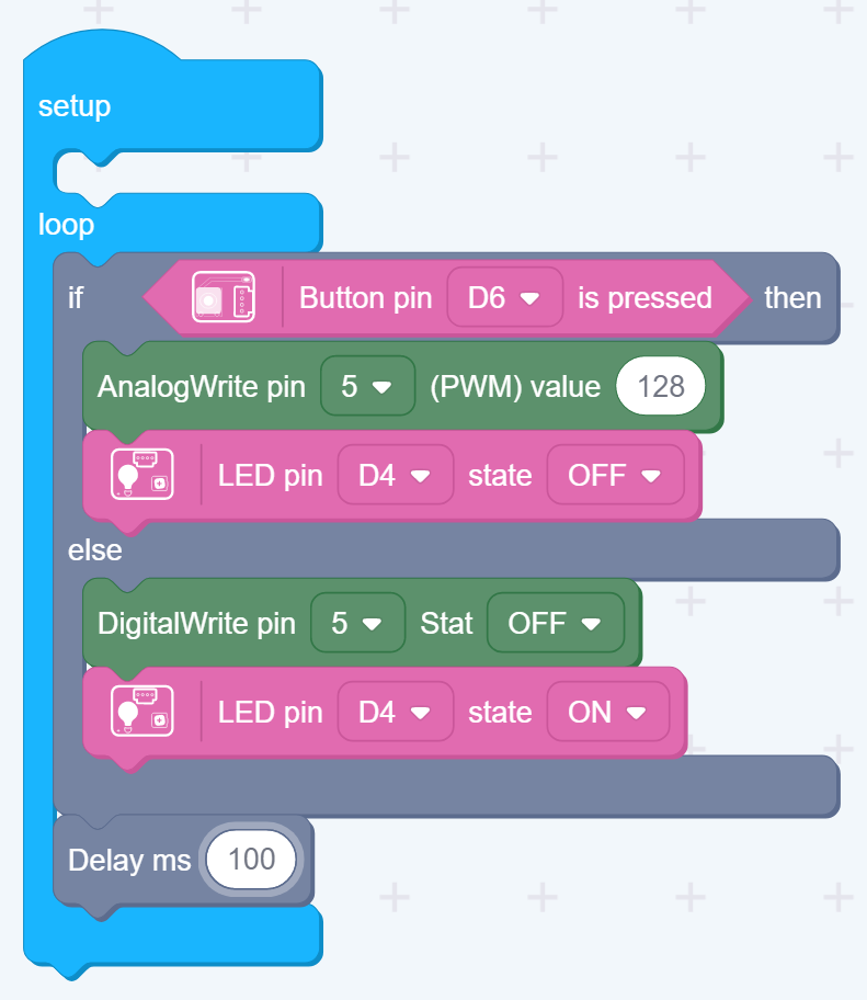
For this lesson, the buzzer sounds when the button is pressed. The LED lights when the button is not pressed.
How to create this …
Watch the video on Youtube:
3. Run the app
Download the app to the board, as in an earlier lesson.
Description:
Writes an analog value (PWM wave) to a pin. Can be used to light a LED at varying brightnesses or drive a motor at various speeds. After a call to analogWrite(), the pin will generate a steady rectangular wave of the specified duty cycle until the next call to analogWrite() (or a call to digitalRead() or digitalWrite()) on the same pin.
Outcome:
The Buzzer beeps.
PWM Usage
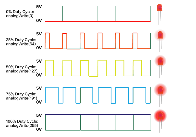
Now that we have learned the use of PWM, in addition to using PWM to control the passive buzzer, we can also use PWM to control the speed of the motor and the brightness of the LED lights and etc.
As the diagram indicates below, use analogWrite() to generate PWM waves, the higher the percentage of Duty Cycle, the brighter the LED.
However, the LED Module on the Grove Beginner Kit cannot be directly controlled by PWM, because the LED module is connected to D4, and as mentioned above, the PWM pins are 3, 5, 6, 9, 10, 11, and pin 4 is not a PWM pin. If you want to control the LED with PWM, you need to pull it down and use the Grove cable to connect to the Grove port with PWM function.
For example, let’s connect Grove-LED to D3 using a Grove cable:
Note
D3 is also inter-connected to the Grove-Temperature & Humidity Sensor, and therefore this example cannot be used with Grove-Temperature & Humidity Sensor together.
Connect the LED to D3 as above.
Implement the program for this as follows:
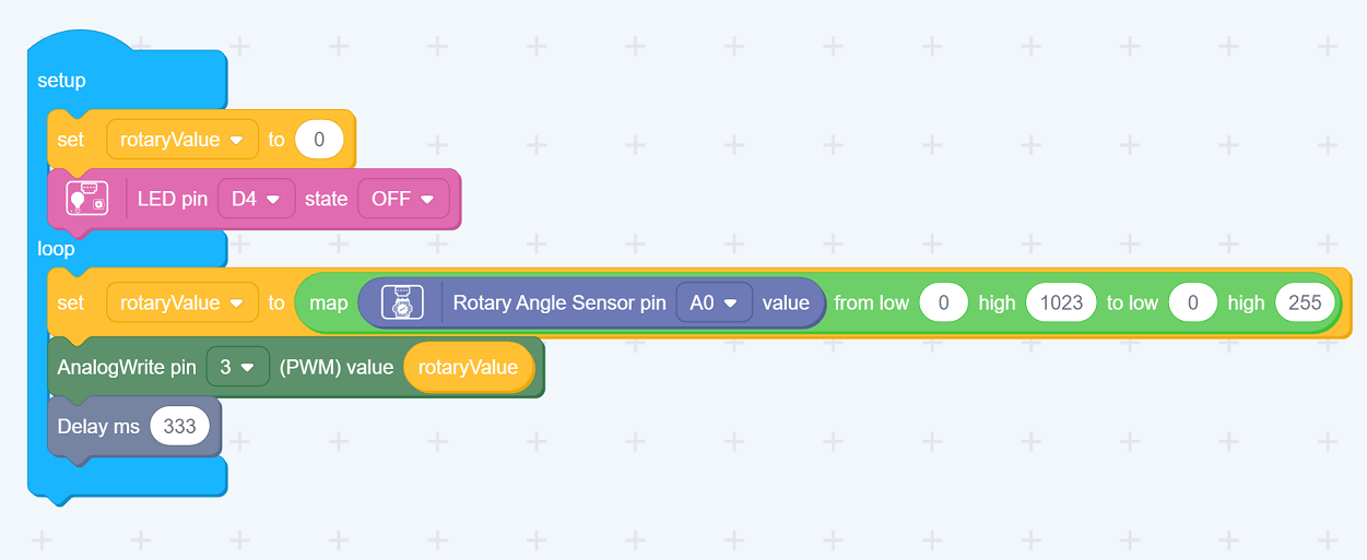
Implement the first part of the loop as above…
Mapping Potentiometer sensor analog signal(0 to 1023)to the brightness of Light(0 to 255).
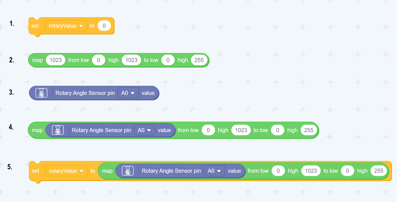
- Get the set-rotaryValue component as previous.
- Get the Map component from the bottom of the operators
Set the second range to 0 to 255, leaving the first as 0 to 1023. - Get the RotaryAngle Sensor as previous
- Drag that onto the Map component as the first parameter on left
- Drag the Map component onto the set-rotaryValue as its input on the right (where 0 shows).
OR Watch a video on ho wto do this:
Remember to set the AnalogWrite pin to 3, for this part of the lesson.
Demo Result:
Adjust the potentiometer to adjust the LED brightness.
All in all, when you want to use the PWM function, make sure to select those pins with a “~” symbol in front of their names.
| Topic | Subtopic | |
| Next: > | Grove Beginner Kit For Arduino | Codecraft Lesson 5 - Light Intensity |
| < Prev: | Grove Beginner Kit For Arduino | Codecraft Lesson 3 - Controlling the Frequency of the Blink |
| This Category Links | ||
| Category: | Grove Arduino Index: | Grove Arduino |