

Softata: SoftataDevice API Version 3.1 - Add DeviceInput Type
softata rpipico firmata arduino csharp grove swagger asp.net blockly api 74hc165
This adds the digital input type to the Softata lower software later. This is useful for polling a switch, as a single input bit, as implemented. There is also a PISO (Parrallel in - Serial out) using a 74HC165 ShiftRegister-In to take 1 or 2 bytes as inputs and serially stream them in using just 3 RPI Pico W pins. This mirrors the Softata Actuator device type for single bit outputs such as a relay or LED, and the 1 or 2 byte input, the SIPO (Serial-In Parallel-Out) using the 74HC595 ShitRegister-Out (which also only requires 3 RPI Pico W pins).
Links
- 74HC165 Data Sheet - Texas Instruments
- SoftataDevices Repository (GitHub) Devices Code
- Softata Repository (GitHub) Middle and Upper Level code.
- Softata Blog Posts
SoftataDevices
SoftataDevice
|
├───Actuator
│       (Grove) Relay
│       Servo
│       Sipo (74HC595) 8/16 Bit Serial In (from Micro) Parallel Out
│       QuadRelay (Generic)
|       (Grove) LED
│
├───Display
│       Bargraph (using Sipo)
│       GBargraph (Grove) Bargraph
│       (Grove) LCD1602
│       (Adrafruit) NEOPIXEL
│       (Grove) OLED096
│
├───Sensor
|       BME280 (Various sources, I2C connection)
│       (Grove) DHT11
|       (Grove) DHTXX (Is an update of DHT11)
│       Simulator
|       (Grove) UltrasonicRanger
│
└───DeviceInput
        (Grove) Switch
        Pico (74Hc165) 8/16 Bit Parallel In Serial Out (To micro)
Connections
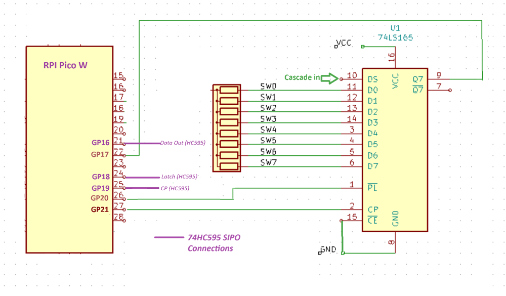
| Function | RPI Pico Pin | 74HC165 Pin | Function | |
|---|---|---|---|---|
| dataPin | 17 | 9 | Q7 | Data out from 165 to RPI |
| latchPin | 20 | 1 | PL | When low data is being sampled. Hi latched |
| clockPin | 21 | 2 | CP | Clock |
| 15 | CE | Connect to Gnd | ||
| 10 | SE | For cascade input ( Q7 from 2nd Shift Reg) |
Tap and rotate phone to enlarge.
Sample Circuit Diagram, connecting to a RPI Uno using switches as inputs. Ref (Modified)
Note: 74HC595 (Serial In Parallel Device connections shown in purple) This SIPO device dovtails, wrt pin connections, with this device.
Usage
When the Softata apps (Console/Blazor/Blockly) run, you choose DeviceInput as the device type then the PISO. You then only have one choice wrt pins, the default, as documented above. Make sure that the 74HC165 is connected as indicated before selecting it as it is then instantiated.
Number of Bytes
The number of bytes that can be read in is two. ReadByte() just reads one byte with one Arduino ShitReg() call. ReadWord() reads 2 bytes with 2 Arduino ShiftReg() calls.This of course requires a second 74HC165s with Q7 of the second connected to Pin 10 DS of the first. The number of bytes is set at 2 in the relevant files but code could be modified to accept any number of bytes.
In GitHub djaus2 SoftataDevices PISO_74HC165.cpp default Setup( ) :
bool Piso74HC165::Setup()
{
  ic165 = new IC_74HC165_ShiftRegister();
  num_bytes = 2;
  return true;
}
That calls the IC_74HC165_ShiftRegister class constructor in [74hc165shiftRegister.cpp](https://github.com/djaus2/SoftataDevices/blob/main/ic_74hc165_shiftRegister.cpp) which calls the _default Setup( ) there:
bool IC_74HC165_ShiftRegister::Setup()
{
  dataPin = 17;   //Q7 Is data out from 165 to micro                165 Pin 9
  latchPin = 20;  //PL When low data is beung sampled. Hi latched   165 Pin 1
  clockPin = 21;  //CP Clock                                        165 Pin 2
                  // CE GND 165 (is enabled)                        165 Pin 15
                  // SE Serial for cascade input                    165 Pin 10
  numBytes = 2;
  numBits = 8*numBytes;
  BitOrder order = LSBFIRST;
  return Setup(NULL,0);
}
There is also a nondefault Setup() in both files. It optionally takes 1,2, 3 up to 5 bytes. If 4 or 5 then that specifies the number of bytes. The other bytes specify the GPIO pin for the data, latch and clock pins respectively. The fifth byte can define the BitOrder which defaults to LSB first.
bool IC_74HC165_ShiftRegister::Setup(byte * settings, byte numSettings)
{
  if (numSettings >0)
  {
    dataPin = (int)settings[0];
    if (numSettings >1)
    {
        latchPin = (int)settings[1];
        if (numSettings >2)
        {
            clockPin = (int)settings[2];
            if (numSettings >3)
            {
                numBytes = (int)settings[3];
                if ((numBytes<1) || (numBytes>2))
                  return false;
                numBits = 8 * numBytes;
                if (numSettings >4)
                {
                    order = (BitOrder)settings[4];
                }
            }
        };
    };
  };
Coding
Generic Commands for a device type are implemnted by all devices of that time, even if just an indication that it is not implemented. That is, a call to these should not generate an error.
Actuator commands have an a_ or A_ prefix Displays commands have a d_ or D_ prefix Sesnsor comamnds have an s_ or S_ prefix DeviceInput commands have a i_ or I_ prefix
#define DEVICEINPUT_COMMANDS C(I_getCmdsCMD)C(I_getDevicesCMD)C(I_getPinsCMD)C(I_setupDefaultCMD)C(I_setupGeneralCMD)
C(i__getValueRangeCMD)C(i_readByteValueCMD)C(i_readWordValueCMD)C(i_PollBitCMD)
C(i_GetnumbitsCMD)C(i_GetInstanceValueRangeCMD)C(i_GetInputCapabCMD)
DeviceInput Generic Commands
Nb: In the Arduino code, a macro is used to turn this definition into an enum list and another macro turns into a matching ordered array of strings.
All Commands starting with an upcase character can be called without an instance being created. Some lowercase prefixed commands have 2 underscore and can be called with an instance.
API Update
In adding this device type and the 2 devices of this type, no code changes were required in the C# Softata class. All code changes were in adding the device type class to the SoftataDevice code, and code for each device of that type. The DeviceInput code was added to the top level Arduino code but no additional code for the actual deviceinput devices in the top level Softata Arduino code was required. This was the objective of the recent refactoring of the device code.
| Topic | Subtopic | |
| Next: > | Blockly | Version Update |
| This Category Links | ||
| Category: | Softata Index: | Softata |
| Next: > | Softata | ngrok update - 1 |
| < Prev: | Softata | API Version 3 |